445 resultaten gevonden
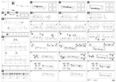
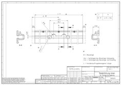
Montagehandleiding Slimchain
Slimchain V1 V2 V3 … 1 … 2 … 2 … 3 148326-02 270 270 A B 300 500 www.geze.com 800 C D E G K L 194 500 260 560 196 498 294 600 360 660 296 598 444 750 510 810 446 748 … 2 … click … 1 … 3 … 6 … click … 5 … 4 click … 1 … 2 … click … 2 … 5 … 5 … ≥S1 ≥S2 ≥N2 300 1160 1200 300 500 1360 1420 350 800 1660 1870 425 4,8 x L ISO 7049 / DIN 7981 M5 x L ISO 7045 / DIN 7985 4,8 x L ISO 7049 / DIN 7981 4,5 x L DIN 7996 Ø 4,0 mm M5 x L (Form SK) Ø 4,0 mm Ø 3,0 mm … 2 … 1 … 2 … 3 … 3 GEZE GmbH Reinhold-Vöster-Strasse 21–29 71229 Leonberg Germany Tel.: 0049 7152 203-0 Fax: 0049 7152 203-310 www.geze.com … 3
(PDF | 4 MB)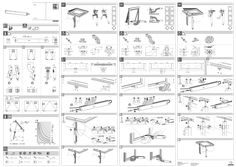
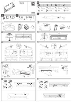
Montagehandleiding E 250
V1 E 250 V2 V3 151932-01 V1 V2 V3 V1 … X … 44 20 30 … 1 4x … 3 … mm … 2 4x … 3 … 3 > 100 kg … 5 4x … 3 … 3 mm 4x … 1 … 1 … V3 … 4 … ≤ 200 x X H … mm … 3 click … 5 … mm 4x 2x … 2 … 7-8 Nm … 1 click … 4 4x 4x … 6 … 4x 7-8 Nm … 2x H > 1000 mm --> X = H/2 4,2 x L ISO 7049 / DIN 7981 M5 x L ISO 7045 / DIN 7985 4,2 x L ISO 7049 / DIN 7981 4,5 x L DIN 7996 Ø 3,5 mm M5 x L (Form SK) Ø 3,5 mm Ø 3,0 mm GEZE GmbH Reinhold-Vöster-Strasse 21–29 71229 Leonberg Germany Tel.: 0049 7152 203-0 Fax: 0049 7152 203-310 www.geze.com 5-6 Nm
(PDF | 4 MB)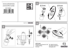
Montagehandleiding universele bodemhuls
2 Universal Bodenhülse universal floor socket Ø 15 mm Ø 13 mm ID 152362 180° … 152371-01 … Ø25 1,5 mm … 042938 52362 … 3 … 34 75 … 1,5 mm 1,5 mm … 1,5 mm GEZE GmbH Reinhold-Vöster-Strasse 21–29 71229 Leonberg Germany 1,5 mm Tel.: 0049 7152 203-0 Fax: 0049 7152 203-310 www.geze.com
(PDF | 843 KB)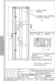
Montagehandleiding doorlopende vloergeleiding voor stangvergrendeling
(PDF | 60 KB)
Montagehandleiding vloergeleiderail binnen voor stangvergrendeling
(PDF | 87 KB)
Montagehandleiding RWA 100 NT met Power lock
RWA 100 NT + Power lock ≥ 199502-00 <1,8 mm 4,2 x L ISO 7049 / DIN 7981 M5 x L ISO 7045 / DIN 7985 4,2 x L ISO 7049 / DIN 7981 4,5 x L DIN 7996 Ø 3,5 mm M5 x L (SK) Ø 3,5 mm Ø 3,0 mm POWER LOCK V2 V1 Power lock Power lock POWER LOCK RWA 100 NT POWER LOCK RWA 100 NT RWA 100 NT RWA 100 NT … 1 M … 2 A A … 3 … A A-A A 4,2 x L (L<10 mm) … 4 POWER LOCK POWER LOCK 1x 2x RWA 100 NT RWA 100 NT 422 10 RWA 100 NT RWA 100 NT solo 60 30 RWA 100 NT 30 378 A 20 75 40 syncro E 250 NT 110 E min. … min. 40 E 250 NT min. … 10 14-24 Ø5 - Ø4,8 100 [ syncro 2x ] 25 G 50 45 < 1,2 m² = solo 20 2x 520-1700 mm 520-1700 mm 14-24 ≥ 360 mm +284 6,5 22 M10 ≥ 1,2 m² = syncro E 250 NT 800-2400 mm ≥ 520 mm 47 520-1400 mm … a ≥ 800 mm 520-1600 mm 100 E = 396 mm b b G G=180 mm b=30° E G=130 mm b=34° G=80 mm b=42° 300 E = 600 mm b G=730 mm b=32° G=680 mm b=33° G=630 mm b=35° G=580 mm b=38° G=530 mm b=40° 150 E = 447 mm … G=330 mm b=30° G=280 mm G=480 mm b=43° G=230 mm b=38° G=430 mm b=47° b=34° b … G=180 mm b=43° … G=380 mm b=51° … 200 E = 498 mm G=430 mm b=33° b G=380 mm b=36° G=330 mm b=39° G=280 mm b=44° GEZE GmbH Reinhold-Vöster-Strasse 21–29 71229 Leonberg Germany Tel.: 0049 7152 203-0 Fax: 0049 7152 203-310 www.geze.com 40
(PDF | 3 MB)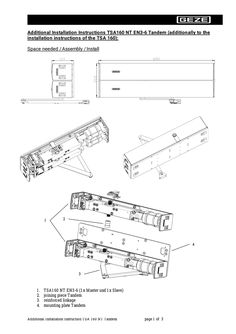
Extra montagehandleiding Tandem TSA 160 EN 3-6
Additional Installation Instructions TSA160 NT EN3-6 Tandem (additionally to the installation instructions of the TSA 160): Space needed / Assembly / Install … 2 … 3 1. 2. 3. 4. TSA160 NT EN3-6 (1x Master und 1x Slave) joining piece Tandem reinforced linkage mounting plate Tandem Additional Installation Instruction TSA 160 NT Tandem page … of … Adjusting the drive: Before adjusting the speeds and the damping at the TSA 160 NT Tandem the control valves on both drives must be adjusted identically. For that follow following procedure: (the below table can be used) Below drive: 1. Turn Valve1,2,4,5 till closed position 2. Open Valve 1,2,4,5 to delivered position Upper drive: 3. Turn Valve 1,2,4,5 till closed position 4. Adjust the Valves to the same position as on 2. of the below drive Below drive Valve No. Upper drive X Rotations X Rotations X Rotations X Rotations Closed Open Closed As below drive … 2 … 5 The setting of the speed and the damping at the specific valves must be done evenly on both drives. This concerns also the setting of the spring force. For example if ÖD has been moved ½ Rotations than ÖD must be changed the same way at the below drive. Additional Installation Instruction TSA 160 NT Tandem page … of … Range of use: Additional Installation Instruction TSA 160 NT Tandem page … of 3
(PDF | 191 KB)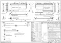
Montagehandleiding Iso glazen vleugel Slimdrive SL/ SL- FR- 2M/DUO/RWS/LL
(PDF | 505 KB)

Montageplaat
Voor E-glijrail, niet-scharnierzijde

Montageplaat
Voor R-glijrail BG